OF SOUTH AUSTRALIA INC
Repair of Smiths Pin Clock
CE 3120/3123 series
Commentary by the late Graham Robinson,
Hillman Owners Club of Australia
OF SOUTH AUSTRALIA INC
OF SOUTH AUSTRALIA INC |
Repair of Smiths Pin Clock CE 3120/3123 series Commentary by the late Graham Robinson, Hillman Owners Club of Australia |
OF SOUTH AUSTRALIA INC |
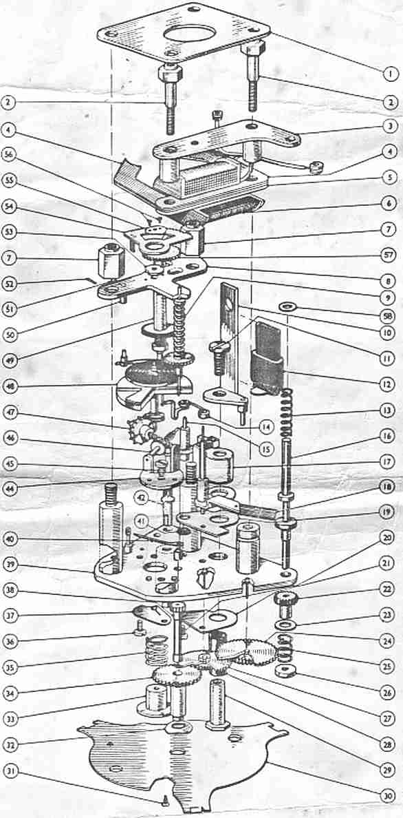
Failures of these clocks as used in Humber Snipes, Hawks, Alpines and maybe Hillmans are many and causes are varied. Refer to Fig. 6 (exploded parts view) below.
Main cause is the carbonising of the offset pin on the balance wheel (48) and the corresponding contact pin (14) that sits on a fulcrum post.
Second cause is incorrect polarity applied when installing causing the rectifier bridge (17) and other items to be burnt out, rendering the clock inoperative. White rectifier assembly (17) is negative ground where Green rectifier assembly (17) is positive earth.
Third is that any loose posts (15/10 & 19/21) within the clock itself will cause shorting to ground and cause carbonising in other areas. Balance wheel hairspring (48) is one.
Fourth is when the earthing pin (16) to start the clock is used too often and particularly if any loose posts (15 & 10) are prevalent will cause secondary burning or carbonising throughout the clock mechanism.
Minor adjustments to the circuit can circumvent a lot of these problems.
One is to install a separate switch to disable the clock when not in use or when standing for long periods. The second is to fit a small power diode (EM401) across the rectifier assembly (17) protecting it and the clock from spurious voltage sparks that causes carbonising. Lastly a suitable capacitor 10uf 25V also fitted to ground from the rectifier assembly will reduce sparking and noise if a radio is fitted.
It is prudent to have the offset balance wheel cleaned every couple of years to stop carbonising, where possible.
Or one could fit a Kienzle or other quartz movement into the housing. I believe some Rover clocks are also compatible.
 |
|
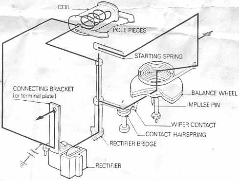
When the starting spring is brought into contact with the rectifier bridge it completes the circuit and energises the pole pieces causing the balance to deflect.
When the spring is released current ceases to flow in the coil allowing the hairspring to return the balance.
The wiper contact and impulse pin now take over the function of supplying the current pulses to the coil as the balance oscillates.
Grant Rodman of the Jaguar Car Club of Tasmania read this article, and kindly submitted his own
commentary on Changing the Polarity of a Smiths Pin Clock.