OF SOUTH AUSTRALIA INC
Two Stroke Diesel Engine
OF SOUTH AUSTRALIA INC
OF SOUTH AUSTRALIA INC |
Two Stroke Diesel Engine |
OF SOUTH AUSTRALIA INC |
This page was previously featured at
Harrington Coachwork.
It is displayed here by permission of Nick Webster, author and webmaster of www.thcoachwork.dsl.pipex.com.

Have you got it yet? The engine has three cylinders situated above and across the plane of the crankshaft. Each cylinder contains two pistons with the crown facing inwards. On each side the pistons are linked to the crankshaft via a short connecting rod, a substantial rocker arm and a secondary connecting rod. Unlike a petrol engine, a two stroke diesel cannot use crankcase pressure to boost the air supply, because it would tend to combust any oil that was entrapped in the air. A Roots (not Rootes) blower (i.e. rotating lobe type) is situated on the front of the engine and supplies the combustion air. The total displacement is only 3.25 litres, but the engine develops 90 B.H.P. Contemporary four stroke engines, for example the Gardner 5LW produced this kind of power from 8 litres. The engine was introduced in 1954 and power outputs were progressively increased. The engine was discontinued when the Rootes Group was taken over by Chrysler in 1968. At the time a four cylinder prototype version was under test and this never made it to production. An example of the TS4 can be seen in the Leyland Historic Commercial Museum in Lancashire, England. A schematic view of the operation of the engine is given, below.
 |
Figure 1 shows the pistons commencing their compression stroke. The exhaust piston has a slight lead over the air piston, thus the exhaust ports are closed whilst filtered air is still entering through the air ports. The design of the latter causes the air to swirl as it enters the cylinder to aid complete combustion. In normal operation the blower increases the pressure of the inlet air chest to about 6 p.s.i. above atmospheric. When the inlet ports close, compression commences. |
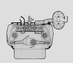 |
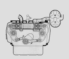
Figure 2 Shows the pistons at inner dead centre (this is equivalent to top dead centre on a vertical engine). Shortly before the pistons reach this position an atomized spray of fuel oil is injected into the cylinder and this is ignited by the intense heat generated by the compression of the air charge. The resulting pressure forces the pistons apart to provide the power stroke. |
 |
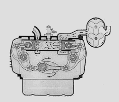
In Figure 3 the pistons are approaching outer dead centre (the equivalent of bottom dead centre on a vertical engine). The exhaust ports open first and the exhaust gases are released causing an initial drop in pressure within the cylinder, known as "blow down." |
 |
In Figure 4 the pistons have reached the extreme of their outward movement and the air ports are open. Blow down ends and air from the blower swirls into the cylinder towards the exhaust ports, thereby scavenging the exhaust gases. This continues until the pistons have passed on through outer dead centre position, the exhaust ports close and the pistons start another compression stroke. The cycle is then repeated. |
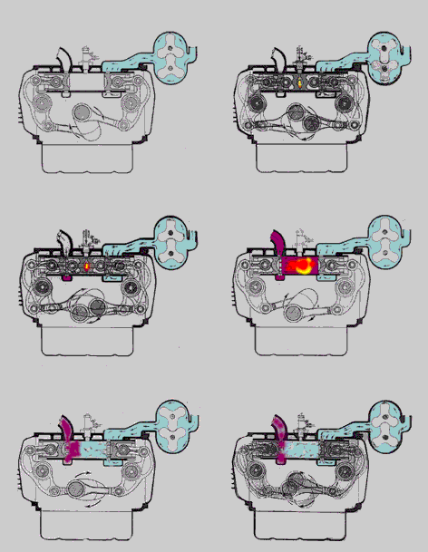 |
Finally, you consult the Roobarb & Custard school of animation and end up with a working model something like this. |
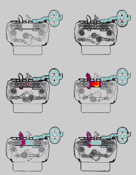 |
The animation, slowed to 10% speed for modern computers. |